To make the auto cut off device you will need:
One high current
12 volt relay (A 30 amp bosch automotive horn relay is what I use but anything
similar will do.)
One momentary
push on switch (where the switch is on only while you press it and is off
at all other times)
About 1 foot
of battery wire
One pair of
battery connectors
One 1/4 watt
or larger resistor approx. 30 ohms (more about this later)
A few pieces
of small hook up wire (any small wire will do)
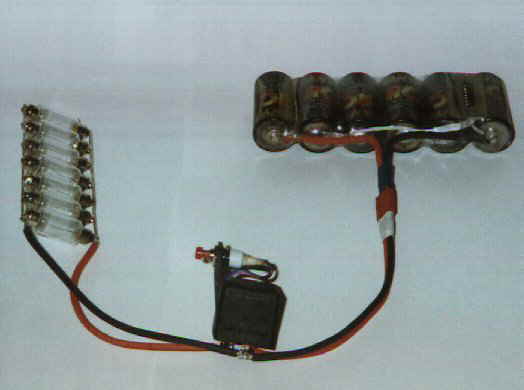
The first step is to wire up the main current loop using standard battery wire, locate one of the coil terminals and solder two pieces of wire (black) to this (one to go to battery negative and one to go to the discharger load negative). Then locate the common terminal and the normally open terminal of the relay (these terminals are open circuit when the coil is not activated and short circuit when the coil is activated) and solder one piece of wire (red) to each of these. Each pair of red and black wires can now have their battery connectors attached.
To check the first stage of the circuit, first measure the resistance between the pair of wires that plug into the battery and the pair that plug into the load they should both be infinite (open circuit) if they are not recheck the circuit and fix any problems.
If this checks out ok the battery can be plugged in. At this stage nothing should happen (if there are flames explosions etc. something is wrong). By using short piece of small wire energize the coil by connecting the unused end of the coil to the positive of the battery (where the switch is on the diagram). When this wire is applied the relay should turn on and the load wires should have 7.2 volts across them, as soon as the wire is released the relay should go off and the voltage across the load wires should go to zero. Once again if the load voltage does not go to zero when the wire is removed check and fix the circuit before continuing. If this works ok the switch can be soldered into position between the two terminals just used.
The next step
is to calculate the size of the resistor needed, to do this first measure
the resistance of the coil (it should be about 100 ohms). Then the voltage
at which the relay releases has to be found, this is done by soldering
a temporary piece of wire in place of the resistor and discharging a battery
while monitoring its voltage (press the switch to start discharging). The
battery voltage at the moment the coil releases should be around 4 volts.
The resistor
value can then be calculated using:
R = Rr(Vc/Vr)
- Rr
Where:
R is the resistor
value Rr is the resistance of the relay coil (around 100 ohms) Vc is the
cut off voltage required (I use 5 volts for a six cell pack) Vr is voltage
at which the relay releases (around 3.5 - 4.5 volts)
This size resistor can then be placed in the position shown on the diagram in the place of the temporary wire used in the previous step.
The discharger should now switch off at around the voltage calculated. All you have to do to use the device is plug in the load and battery and press the switch once to start discharging.
Alternatively a variable resistor can be used in place of the resistor to trim the cut off voltage. If you have room in the plastic case of the relay the resistor and switch wires can be placed inside (as I have done), this makes the devise much neater and less prone to damage. The switch can also be mounted on top of the relay. The excess terminals on the relay can then also be removed leaving only three (negative, bat positive and load positive).
Once the cut off trips the battery is completely isolated so it can be left connected for extended periods of time, however as always the load should not be left unattended while it is operating as it could set fire to something due to heat build up. I find mine very useful for racing as it only takes a few seconds to plug in after a race before going out to marshal the next race, when you get back the battery is dumped and ready to be recharged.
![]()