The servo driver is a simple device about the size of a standard receiver, it uses a single I.C. to simulate the output signal of a receiver to drive servos and ESC's. It is most useful on race days if your handset is confiscated while your not racing or if you're on the same frequency as someone else, it allows you to test servos and speed controllers without using a handset/receiver.
You simply plug in the ESC or servo and battery, a knob on the device controls the position of the servo (in exactly the same way as the wheel on a pistol type radio) without the risk of interfering with another driver using the same frequency.
To learn more about how your transmitter and receiver work click here.
To make the servo driver you will need:
Integrated circuits
Resistors (help?)
Capacitors (help?)
Diodes
Miscellaneous

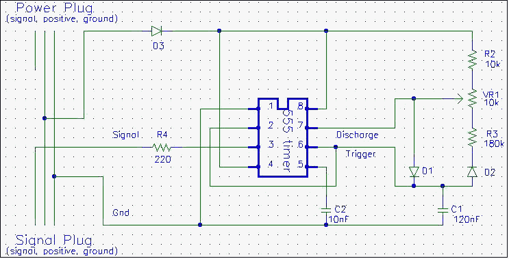
The circuit is basically an astable 555 timer with a slight change to the charging/discharging circuit (the bit to the right of the IC). Usually the charging/discharging circuit consists of two resistors and a capacitor but when it is wired in this way the output has to be 'high' (5v) for longer than it is 'low' (0v). Since this circuit requires the output to be high for only 2ms every 20 ms some alterations had to be done, the use of the diodes effectively separates the charging and discharging circuit so that the output can be high for any fraction of the total cycle time.
To see how this circuit works first assume the output is high and discharge is floating (not shorted to ground), current flows down through R2, the top half of VR1 and through the diode D1 and through the capacitor C1. As this happens the capacitor charges until it reaches 2/3 of the supply voltage, this triggers the 555 timer to change state, the output goes low and discharge becomes shorted to ground. Current then flows out of the capacitor through D2, R3 and the bottom half of VR1 into the discharge pin until the capacitor voltage reduces to 1/3 of the supply voltage. This causes the 555 timer to change back to the original state starting the cycle again. The time the circuit is high and low is approximated by these equations:
This gives a high time of 1-2 ms and a low time of 18-17 ms respectively depending on the position of the variable resistor, this accurately simulates the output of a receiver. Note as the variable resistor is turned 'down' the high time is increased and the low time reduced by exactly the same amount always giving the same total cycle time.
The construction process is fairly simple, simply solder the complete circuit together either using a home made PCB or a prototype board. All the components are soldered directly on the board except the trim-pot, which is mounted in a suitable sized hole and then connected using short fly leads. Close attention must be made to the IC, diodes and the servo plugs as these are polarised. The plugs must be placed around the right way, and it varies for different brands of receivers, work out which is positive, ground and signal before constructing the circuit.
Once it is all constructed some testing can be done, first measure the resistance between the positive and ground pins, if it is large (it should be about 10 kohms or more, mine is 15kohms) a 5v battery can be connected. Once the battery is connected measure the ground to signal voltage, it should be about 5-10% of the battery voltage and should change within this limit as the variable resistor is adjusted. If this is ok connect an old servo (recheck the order of the pins before you plug it in), it should move slightly as you do, if it turns fully in one direction and starts to strain quickely disconnect it before any damage is done. This means the pulse is either too long or too short and there is probably an error in the circuit. If it does not strain turn the variable resistor and it should follow it (without hitting the travel stops), if it does the circuit is complete if not disconnect the servo and re-check the circuit.
If you have access to an oscilloscope you can check the output of the circuit before you plug in a servo, the signal should produce a positive pulse of 1-2 ms (adjustable using the variable resistor) every 20 ms.
If everything works ok you should now be able to use it on both servos and ESC's. To test an ESC just plug it into the signal socket (with nothing plugged onto the power socket), to test a servo plug the ESC or a 5v battery pack into the power socket, and the servo into the signal socket. If you want to you can extend the circuit to include two signal sources so that when the servo and ESC are plugged in both can be adjusted individually. Also small variable resistors can also be placed in series with R2 and R3 to precisely set the end points of the servo throw (replace R2 with 8.2k + 5k var and R3 with 160k + 50k var).
NOTE If a ESC is being used on the signal plug a battery must not be attached to the power plug. The ESC powers the whole circuit as it does normally with a receiver.

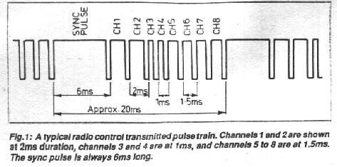
The receiver
then decodes these pulses, it has a counter that resets every time it receives
the sync pulse. It sends the first pulse after the sync pulse to channel
one, the second to channel 2 etc all the way up to channel 8. This gives
each servo a pulse of between 1 and 2ms about every 20ms, the time between
the pulses is not important, it is only the length of the pulse that determines
the position of the servo. A 1ms pulse positions the servo to -45deg, through
to a 2ms pulse for +45deg.

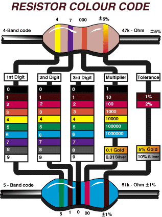
Just line your
resistor up with the chart and read off the numbers. Note there will be
one colour band further apart than the others, this is the tolerance band
and goes to the right as shown. Your resistor may have four or five colour
bands, the ones with five bands are the new metal type resistors, the are
more accurate and usually more expensive -- about $0.02 :-).

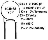
There are two main methods used to encode the value of the capacitor, the first can be seen below, the first three numbers give the size, the rest refer to other characteristics. They work in a similar way to resistors the first two are the first two digits and the third is the multiplier, giving the value in pF, where 1 F (Farad) = 1000 mF (milli Farad) = 1,000,000 uF (micro Farad) = 1,000,000,000 nF (nano Farad) = 1,000,000,000,000 pF (pico Farad).

The other method
is to print the value directly on the capacitor, ie 10n = 10 nano-Farad.

Negative        Positive        Signal

-------------------------------

Black           Red             White

Brown           Red             Orange
If you're not sure check with a multimeter, positive is 5-7.2 volts, signal is about .4 Volts (7.5% duty cycle) referenced to ground. (don't short anything out if you check it and no I won't be replacing anything if you stuff it up)
A 555 timer basically works by monitoring the voltage on pin 6 (trigger) when this goes above a preset level (2/3 of the supply voltage) it shorts pin 7 to ground and sets the output low. It then remains in this state until the trigger voltage gets to below 1/3 of the supply voltage causing the discharge pin to be disconnected from ground and the output to go high.

The pin-outs
of a single 555 timer can be seen above it comes in a package similar to
the picture on the (except it only has 8 legs). Note the notch on the top
of the pin-out diagram and the top right of the I.C. this is used for working
out the numbers of the pins. The pins are numbered in an anti-clockwise
direction when looking from above, starting with pin 1 to the left of the
notch (ground) through to pin 8 to the right(+Vcc).

If you haven't made you own PCB (printed circuit board) before the easiest thing to use is a prototype board, these are available from electronics stores for under $5. As the name suggests they are used for making prototype of circuits when you haven't got the time to make an individual PCB they come with all the holes drilled an a grid pattern of tracks, IC's and other components will simply slot into position ready for soldering. To make the tracks you simply use solder to join or a knife to cut the tracks already etched onto the board to complete the circuit you want.
A tip for young players: The components are put in from the blank side that does not have the tracks and soldered from below.